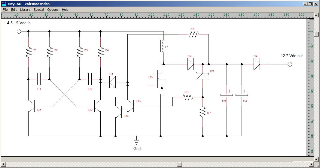
So, how does it work?
For any who have
no electronics knowledge all you really need to know about the different components is:
RESISTORS allow current to flow, but not as well as wire. When a current flows in them you get a voltage drop from one side to the other (like a bad earth on a car, but deliberate)
CAPACITORS act like (small) stores of electricity. When they're connected to a voltage they charge up, then release electricity when disconnected.
DIODES let current flow one way, but not the other. In the circuit diagram they let current flow when the "arrow" of their symbol is pointing from positive to negative. If the voltage is reversed they take a few thousandths of a second to block it. If you put enough reverse voltage across them they break down and conduct both ways.
SCHOTTKY diodes are the same, but act
very fast to block current trying to flow the "wrong way".
ZENER DIODES are special diodes that are used "backwards". They have low, and carefully set, reverse breakdown voltages and you use them by deliberately putting a reverse voltage across them. When that voltage rises to their breakdown voltage they start to conduct, which gives you a known voltage reference.
TRANSISTORS act as electrically controlled switches (a bit like electrical relays). There's a fair bit more to them than that really but in this circuit it's that simple switching that matters.
INDUCTORS (L1) act like coils in ignition circuits. If you connect them to a current supply they build up magnetism in their core. If you then stop the current suddenly, the magnetism collapse and that generates a high voltage "spike" in their windings.
So, to the circuit itself:
The parts to the left of D1 in the circuit make up a "standard" astable multivibrator. This is a textbook circuit which is, as the name suggests, unstable. In the astable circuit, the transistors are connected so that when one is on, it tries to turn the other one off but, when one is off, it tries to turn itself back on. So, they keep switching alternately. The effect is that the left-hand end of D1 keeps switching between 6v (the input voltage) and ground. In this case, they're set up (by the values of R2, R3 and C1, C2) to switch at about 3200 time a second.
Moving on now to Q5 - the MOSFET. This will let current flow through the coil to ground ONLY if there's a voltage on the terminal connected to D1. Ideally, it needs 10v to turn on fully, but that's not available immediately. D1 will, initially, allow a small amount of current to flow backwards when it's left-hand end is switched to 6v by the astable. This is enough to allow a very small pulse of current through L1.
As soon as D1 blocks, the current stops flowing and L1 (the coil) produces a small spike of high voltage. This voltage pushes a current through D2 (the onll way it can flow) and charges C3 and C4 a little bit. This gives enough voltage to go back, through R5, and turn the MOSFET on again.
Now, the MOSFET is being turned on by voltage from the output side of the circuit, and current starts to flow in the coil again. But, the astable keeps switching the left end of D1 between earth and 6v. When it switches to earth, D1 has voltage the "right" way across it and acts like a short-circuit between the MOSFET's control connection and earth. So the MOSFET turns off. This causes another spike in the coil, which charges C3 and C4 a little more.
Now there's enough voltage back to the MOSFET (through R5) to turn it on fully
as long as the left side of D1 isn't connected to earth. So now, the MOSFET will start switching on and off at the same speed as the astable is switching the left side of D! - about 3200 times a second. That gives 3200 spikes from the coil every second to keep "topping up" C3 and C4.
Left to itself, the circuit at that point will keep increasing the voltage at the output to whatever the
peak voltage of the spikes from the coil is. That's around 80v in this circuit, and it'll reach that in a few tenths of a second!
So, we have D3 (the zener diode) and Q3 / Q4 to stop it. How they act is: When the output voltage gets above 12v the Zener diode starts to conduct. This allows current to flow through it, through R6 and into Q3 / Q4. These are two transistors wired up so that they turn on very fast with a very small input. As soon as they turn on, they act as a short circuit between the control ("gate") terminal of the MOSFET and earth. This turns the MOSFET off (like D1 did earlier), and keeps it off as long as Q3 / Q4 are on.
As soon as the output voltage drops below 12v (because something is using power from the output), the zener diode stops again and Q3 / Q4 turn off again. This leaves the MOSFET free to start switching again and "top up" the output back to 12v.
That's a fairly non-technical description but hopefully gives an idea how it all works.
Bottom line is: 6v in and 12v out, so we can use a few modern luxuries without converting the main elecrical system


 ) I've added a simple relay board for that which gives two 12v outputs which are disconnected from each other when the power's off. That way, the battery can be connected to one and a "permanent" 12v supply taken from it, while the other one only goes live when the unit's switched on (with the car's ignition) - to give a 12v "ignition live" wire without messing around with the ignition switch.
 )and also try to find time to write up some build instructions for anyone who wants to give it a try but hasn't done stuff like this before.

